RS Switchboard cabinets with IP 40 and IP 54 covers
Switchboard cabinets are designed for the installation of electrical equipment and completion with electrical switchboards. They are made with IP 40 covers, marked RS 40 … and IP 54 covers, marked RS 54 …. Switchboard cabinets are made according to ČSN EN 62208 standards. Operation conditions normal according to the standards. Electrical continuity ensured by the conductive parts of the cabinet.
The switchboard cabinets can be delivered empty, with required adaptation according to the requests submitted or alternatively with the equipment. The switchboard is of modular type. The system enables you to make a combination of one or more fields, where individual frames are connected with each other by means of connection sets. By adding side covers or using transient parts, corner boxes and in- between fields, the whole field becomes complete.
In addition to its low weight, the switchboard cabinet has a very steady construction, which is even strengthened by internal profiles.
CONSTRUCTION OF SWITCHBOARD CABINET
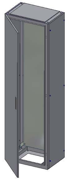
The solid base of the cabinet is made of welded steel sheet of thickness 2 mm, which consists of upper and lower lid, front and rear stands. The stands are connected in the middle by stiffeners. At IP 54 cover a profile seal by EMKA company is slipped onto the door opening. The rear cover is removable.
The door is made of steel sheet of thickness 2 mm and it is reinforced around the perimeter by a mounting rail. It can be right or left and it is attached to the weldment by three hinges. The door can be locked by a three- point bolt lock (the customer can be delivered a swivel handle lock). The door can be fitted with a glass window ( two-layer safety glass, thickness 6 mm or tempered glass, thickness 4 mm).- type RSP.
The holes in he upper and lower lids serve as outlets, a cable holder can be screwed to the lower lid where can be located cable holders. The sliding partitions screwed to the lower lid adjust the space for the wiring. (IP 40 version has only a hole without partitions- these can be ordered if necessary). A removable top cover is screwed to the top lid.
The switchboard cabinet is equipped with grounding screws and four holes in the bottom lid for screwing the base. There are four holes in the top lid for eyebolts to make the transport and handling as easy as possible. The maximum load of installed appliance is 300 kg. The holes are sealed by plugs.
Inside the cabinet there is a 25 mm raster, which makes the whole process of fitting the cabinet with devices easier.
The surface treatment is carried out by a high quality abrasion resistant powder coating- komaxit, colour shade RAL 7032. Other colour shades within RAL scale are available at a customer´s request.
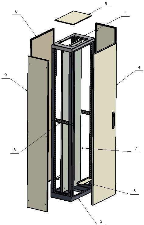
1.Ceiling
2.Bottom part
3.Perforated reinforcement
4.Door
5.Top lid
6.Rear lid
7.Mounting panel
8.Bottom cover
9.Side lid
OPTIONAL ACCESSORIES
Mounting panel
- thickness 2.5 mm
- galvanized metal
Side lids
- mounting on the sides of the cabinet (the total width of the switchboard cabinet will increase by 50 mm after screwing on two side lids. )
Base for the switchboard cabinet
- is intended for anchoring the cabinet and easy installation of cables
- has removable side covers
- height 100, 200 mm (other heights according to the customer´s specification
- coating RAL 7016
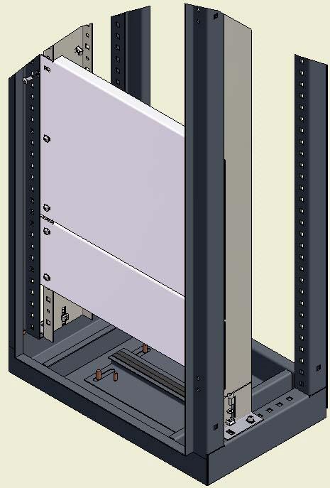
Device frame 19"
- Device frame 19"
- designed for devices of widthwise module 19"
- devices are attached by screws and nuts M6
- coating RAL 7032
- devices can be mounted on a grid, mounting panel or combination of both
Mounting rails
- designed to attach devices
- attached by screws, nuts and connecting pieces
- coating RAL 7032 or galvanized sheet
Door
- can be right or left
- full (glass door on request)
- rear lid can be replaced by the second door- RS cabinets ... 2D
- double door with cabinets wider than 1000 mm- RS cabinets ... 2K - can be equipped by grids and fans on request
Rear lid
- mounting on the back side of the cabinet
Shelves
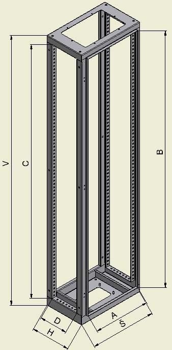
The total depth of the switchboard including the door and rear lid is 50 mm greater than the dimensions stated in the table (dimensions of the switchboard frame).
The switchboard cabinets comply with the requirements of technical standards and the manufacturer guarantees conformity of all products of the particular type available on the market with technical documentation and requirements of applicable government regulations.
Cabinet
- steel sheet, welded, 2 pcs. of reinforcement of RV1 cabinet
- IP54 with sliding partition on the bottom lid for cable
- holes for eyebolts
Door
- reinforced with mounting rails, three-point lock (another alternative possible
- cabinets 1000 mm wide or more
- double door RS-2K
Inlets for cables
- bottom and top
Surface treatment
- powder coating, colour shade RAL 7032 or another within RAL scale
Optional accessories
- eye bolts, cable holder, sliding partitions for RS40 ...
Types of RS distribution cabinets:
RS - distribution cabinet
RSP - glass distribution cabinet
RS-2D - two- door distribution cabinet
RS-2K - two-wing distribution cabinet
|
Typ |
V |
Š |
H |
Typ |
V |
Š |
H |
|
RS .. 1664 |
1 600 |
600 |
400 |
RS .. 2084 |
2 000 |
800 |
400 |
|
RS .. 2108 |
2 000 |
1 000 |
800 |
RS .. 2085 |
2 000 |
800 |
500 |
|
RS .. 1864 |
1 800 |
600 |
400 |
RS .. 2086 |
2 000 |
800 |
600 |
|
RS .. 1884 |
1 800 |
800 |
400 |
RS .. 2104 |
2 000 |
1 000 |
400 |
|
RS .. 2064 |
2 000 |
600 |
400 |
RS .. 2105 |
2 000 |
1 000 |
500 |
|
RS .. 2065 |
2 000 |
600 |
500 |
RS .. 2106 |
2 000 |
1 000 |
600 |
|
RS .. 2066 |
2 000 |
600 |
600 |
RS .. 2108 |
2 000 |
1 000 |
800 |
V - height, Š - width, H - depth ( in order to get the real depth incl. the door and the rear lid, you have to add 50 mm)
Nový typ RS
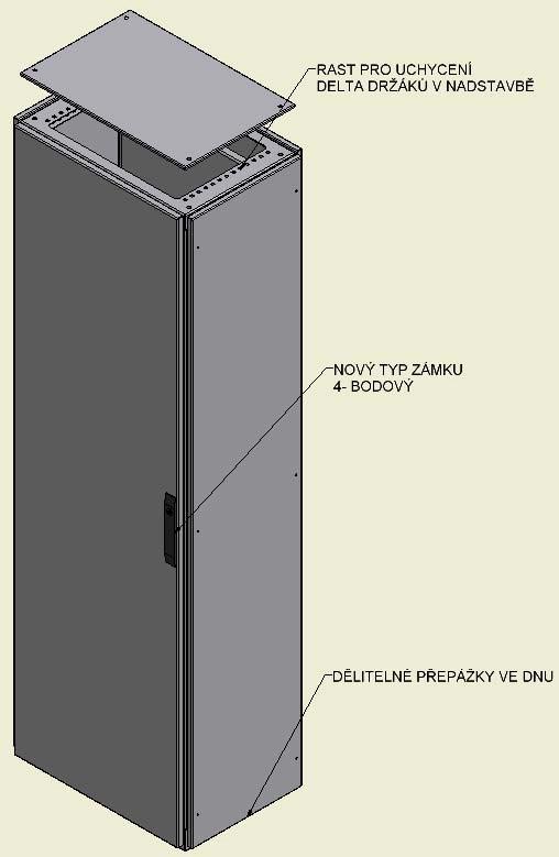
V současnosti přechází výroba rozvaděčů typu RS na modernizovaný typ, který se liší od předchozího modelu v několika bodech:
- typ zámku (4 bodový)
- v nadstavbě byl přidán rast pro uchycení delta držáku byly upraveny dělitelné přepážky ve dnu
Pozn.: na vyžádání je možno použít i starý typ.
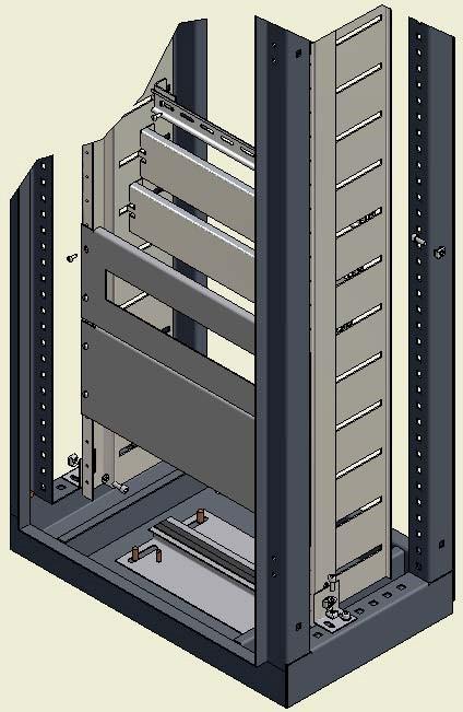
Stavebnicový systém přístrojových roštů
Je tvořen nosníky přístrojového roštu, držáky DIN lišt a spojovacím materiálem.


Nosník přístrojového roštu NPR 1 - pevný
Je vyroben z pozinkovaného plechu tl.2 mm. Slouží k pevnému uchycení přístrojových můstků a DIN lišt. Ke skříní se připevňuje pomocí spojovacích kusů (SK3).
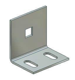
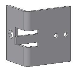
Detail spojovacího kusu SK 3
Nosník přístrojového roštu NPR 2 - posuvný
Je vyroben z pozinkovaného plechu tl.2 mm. Slouží k posuvnému uchycení přístrojových můstků, dle použitého přístroje. Ke skříní se připevňuje pomocí spojovacích kusů (SK3).
Držák DIN lišty - SK 4
Je vyroben z pozinkovaného plechu tl.2mm. Slouží ke snadné montáži DIN lišt do přístroj. roštu. DIN lišta se připevňuje k držáku SK 4 pomoci samořezných šroubů do plechu. Držák lišty se přichytí k nosníku pomoci plovoucí matice a šroubu M6.
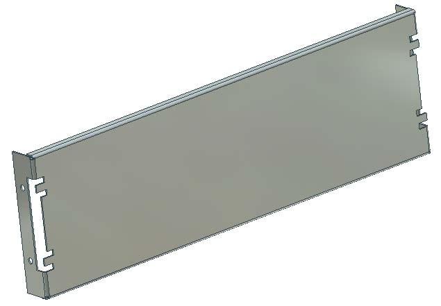
Přístrojový můstek
Je vyroben z pozinkovaného plechu tl.1,5 mm. Slouží k uchycení el. výzbroje, buď přímo (pomocí šroubů), nebo prostřednictvím DIN lišt. Vyrábí se v šířkách 75, 150 a 300 a v délkách dle šířky použité skříně. K nosníku se připevňují pomocí plovoucích matic a šroubů M6.
M 150/600 Přístrojový můstek vysoký 150 mm, do rozváděče širokého 600 mm.
Na přání zákazníka zhotovíme i atypické rozměry.
-
M75/600
M75/800
M150/600
M150/800
M300/600
M300/800
Příklady použití přístrojových roštů a můstků

 CZ
CZ EN
EN